Mohr's Circle: 3D Max Principal Stress
Simply input the components of a 3D stress tensor to instantly solve the cubic characteristic equation, determine the three principal stresses, compute the absolute maximum shear stress, and visualize the complete 3-circle Mohr's diagram with its permissible stress zone.

Date
August 27, 2026Updated
October 16, 2026Category
UIMinutes to read
8 minInput:
fx: fx, fy: fy, fz: fz
fxy: fxy, fyz: fyz, fzx: fzx
Output:
f1: f1, f2: f2, f3: f3, fsmax: tmax
3D Stress Transformation and Mohr's Circle: Theory, Construction, and Applications
1. Overview and Fundamentals
In continuum mechanics and structural engineering, a complete description of the internal forces at any point within a material requires a second-order tensor: the Cauchy stress tensor .
While a 2D (plane stress) Mohr’s circle assumes stresses occur primarily in a single plane, real structural components operate in three-dimensional stress states. The 3D Mohr’s Circle provides:
A complete graphical map of all possible combinations of normal stress () and shear stress () acting on any plane passing through a given point.
The true absolute maximum shear stress (), which is critical for ductile yield criteria (e.g., Tresca).
A geometric interpretation of coordinate transformations without repetitive matrix multiplications.
2. 3D Stress Transformation Theory
2.1 The Stress Tensor
With respect to a Cartesian coordinate system , the stress tensor is defined by 9 components (6 independent due to moment equilibrium ):
2.2 Traction Vector on an Arbitrary Plane
Consider an arbitrary cutting plane defined by its unit normal vector :
The total force per unit area acting on this plane is the traction vector , obtained via Cauchy’s stress formula:
The traction vector is resolved into two orthogonal components:
Normal Stress (): Projection of along the normal :
Shear Stress (): Magnitude of the tangential component:
2.3 Coordinate Transformation
If the coordinate axes rotate to a new orientation via an orthogonal transformation matrix (direction cosine matrix, where ):
3. Principal Stresses and Invariants
There exists a coordinate system where all shear stresses vanish (). In this basis, the traction vector is strictly collinear with the plane normal:
3.1 Characteristic Equation
For non-trivial solutions ():
Where the stress invariants are:
First Invariant ():
Second Invariant ():
Third Invariant ():
The three real roots are the principal stresses, arranged convention-wise as:
4. Mathematical Derivation of the 3D Mohr's Circle
In the principal coordinate system, the normal vector is . The stress formulas simplify to:
Unit normal constraint:
Normal stress:
Squared magnitude of traction:
Treating as unknowns, this linear system yields:
Because direction cosines are real, their squares must be non-negative (). Given :
Since and , implies:
Since and , implies:
Since and , implies:
5. Geometry and Meaning of 3D Mohr's Circle
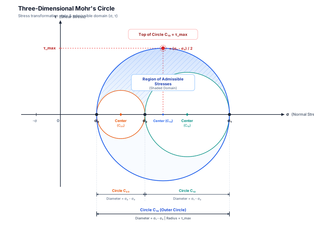
The three inequalities state that any physically possible stress state acting on any orientation must lie inside the region between three circles:
The Three Boundary Circles
Circle | Spanning Principal Stresses | Center | Radius () | Physical Meaning |
|---|---|---|---|---|
to | Stresses on planes parallel to direction | |||
to | Stresses on planes parallel to direction | |||
to | Outer circle: Encompasses all admissible states |
Key Takeaway
The Admissible Domain: Every plane passing through the point exhibits a normal stress and shear stress that falls in the annular region between the three circles (or on their perimeters).
Absolute Maximum Shear Stress: The highest shear stress experienced at the point is the radius of the outer circle:
This stress occurs on planes inclined at to the and principal directions, and parallel to the axis.
6. Step-by-Step Guide: How to Construct and Use 3D Mohr's Circle
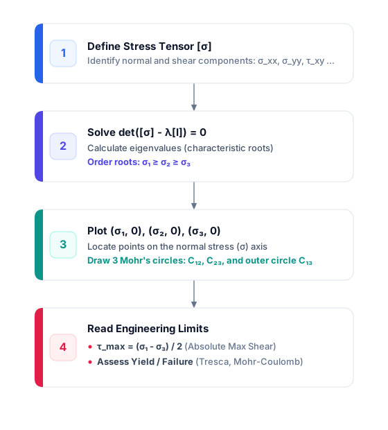
Step 1: Establish the Stress Tensor
Identify the normal stresses () and shear stresses () with correct sign conventions (tension positive, compression negative).
Step 2: Calculate the Principal Stresses
Find the roots of the cubic equation:
Order the roots such that .
Step 3: Draw the Circles on the Plane
Mark points along the horizontal -axis.
Locate the centers:
Draw circle through and .
Draw circle through and .
Draw outer circle through and .
Shade the annular area between the circles.
Step 4: Map an Arbitrary Orientation
To locate the stress state for a plane with direction cosines :
Measure angle relative to the axis.
Draw an arc of constant centered at .
Measure angle relative to the axis and draw an arc of constant .
The intersection of these arcs inside the shaded region gives the exact coordinates .
7. Practical Engineering Significance and Failure Theories
7.1 The "Plane Stress Trap"
In 2D analysis (e.g., thin sheets or surface elements), engineers often evaluate and set the third normal stress to zero: . Calculating only 2D principal stresses and can yield incorrect maximum shear values:
Case 1 (Opposite signs):
The ordered stresses are , , .
(2D formula holds).
Case 2 (Same sign - Biaxial tension):
The ordered stresses are , , .
The true 3D shear stress is:
A 2D analysis would calculate , underestimating maximum shear and leading to non-conservative, unsafe designs.
7.2 Failure Criteria Application
Tresca Criterion (Maximum Shear Stress Theory):Yield occurs when reaches the shear yield limit :
Graphically: Yielding occurs when outer circle expands to touch or exceed diameter .
Mohr-Coulomb Criterion (Brittle / Geotechnical Materials):Accounts for materials with higher compressive strength than tensile strength:
Graphically: Failure occurs if the outer circle touches the envelope line defined by cohesion and friction angle .
8. Worked Numerical Example
Problem Statement
A structural steel component is subjected to the following stress state (in ):
Find:
The principal stresses.
The centers and radii of the 3D Mohr's circles.
The absolute maximum shear stress.
Solution
Step 1: Find Principal Stresses
Since , the -axis is already a principal axis:
The remaining sub-matrix in the - plane is:
Using the 2D transformation formula:
Roots:
Sorting from highest to lowest:
Step 2: Calculate Circle Parameters
Circle (between and ):
Center:
Radius:
Circle (between and ):
Center:
Radius:
Outer Circle (between and ):
Center:
Radius:
Step 3: Identify Maximum Shear Stress
The absolute maximum shear stress is the radius of the outer circle:
(Note: If one had incorrectly performed a 2D analysis on only the - plane, they would have estimated , an error of nearly .)
9. Summary Reference
Property | Symbol | Formula |
|---|---|---|
Principal Stresses | Roots of , sorted | |
Outer Circle Center | ||
Outer Circle Radius | ||
Absolute Max Shear | ||
Hydrostatic Stress | ||
Octahedral Shear Stress |